TYPE EDIT & DATRON Next Controller
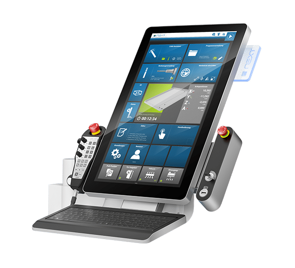
With DATRON and the NEXT Controller, a new type of machine communication has been developped in TYPE EDIT.
Starting from Version 13 Build E, TYPE EDIT can now run a script to drive DATRON machines with the Next Controller. The postprocessor installation presentsed on this page manage as well the 4th Axis motions of the optional attachment allowing to engrave your text, logo, ornaments and any vector on a cylindrical shape.
_____________________________
1.Save the needed Files:
To install properly the machining output with the .simpl format in TYPE EDIT then towards the Next Controller, you will need the following configuration files in either Metric or in Imperial system, accordingly to the unit currently running on your Next Controller.
- DATRON_Next.MAC
- DATRON_Next_Script_V5.txt
ISO / METRIC (.zip)
DATRON_Next_MM.Mac
DATRON_Next_Script_MM_V5.txt
IMPERIAL / INCHES (.zip)
DATRON_Next_IN.Mac
DATRON_Next_Script_INCH_V5.txt
The .MAC file has to be saved in the POSTPROTE folder of TYPE EDIT under C:TypeEdit_V13-LaserType_V13POSTPROTE
The .TXT file has to be saved under the MachiCodec folder of TYPE EDIT under C:TypeEdit_V13-LaserType_V13MachiCodec
2. Postprocessor Installation .MAC in TYPE EDIT:
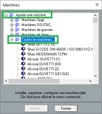
2.3. Click then on the “+” located on the left of “Add a machine” to unwrap the list, then on the “+” also on the left of “All machines…”.
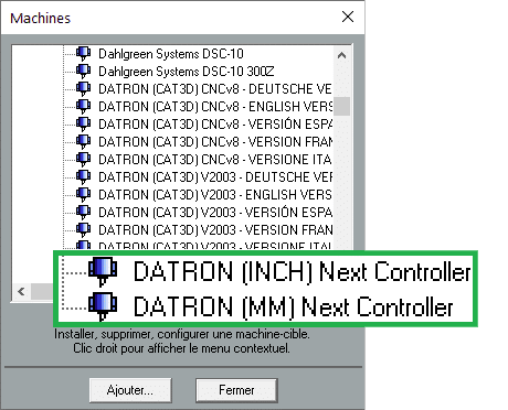
2.4. Look for the Post-processors “DATRON (…) NEXT CONTROLLER” in the list, then select one making sure the Unit presented between parentheses is the good one (INCH) or (MM). Finally click on the “Add” button”.
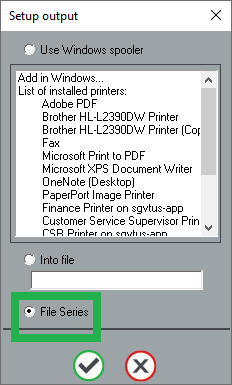
2.5. Continue in “Set Up Output” by making sure “Files Series” is selected before validating the selection with the green tick.
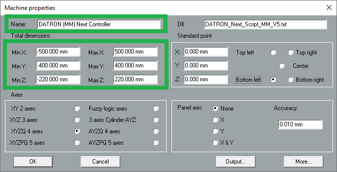
2.6. Modify as needed the “Name” with the one of your DATRON (Neo, M8, ML…):
Below are the names and dimensions of the current DATRON machines:
- DATRON Neo Next : (19.5″ x 15.5″ x 8.5″) or (500 mm x 400 mm x 220 mm)
- DATRON M8 Cube Next : (40″ x 32 ” x 9.5″) or (1020 mm x 830 mm x 245 mm)
- DATRON ML Cube Next : (60″ x 40″ x 9.5″) or (150 mm x 1020 mm x 245 mm)
- DATRON ML Cube Next (LS) : (60″ x 40″ x 9.5″) or (150 mm x 1020 mm x 245 mm)
- DATRON MX Cube Next : (40″ x 33″ x 10.5″) or (1040 mm x 850 mm x 270 mm)
- DATRON M10 Pro Next : (41″ x 35″ x 9″) or (1020 mm x 830 mm x 240 mm)
3. Adding a Cutter in the tool database so it is then added to the output file .simpl:
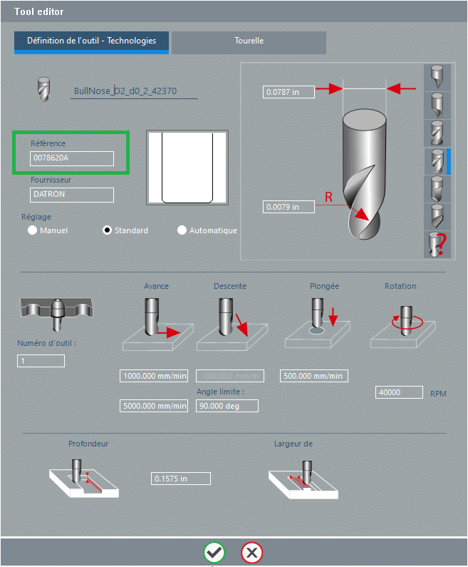
To create and add a DATRON tool, you will need to enter the name as it is named in the next controller of the machine. It checks this field and interacts with its information.
To be noted the field for the tool number is no longer used as in the past with the tool changer. It is now the “Reference” field which is taking care of calling tools.
4. Setting up the Size of the Material (raw) in TYPE EDIT:
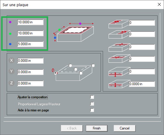
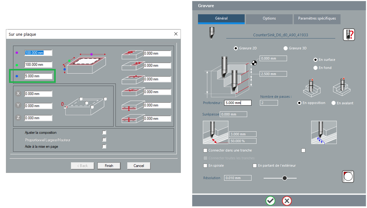
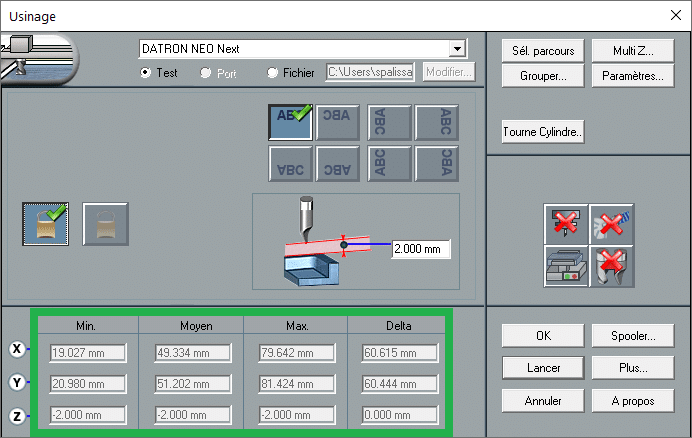
Next Controller checks also the size of the toolpaths generated by TYPE CAM. Toolpaths must be bounded within the Working Area of TYPE EDIT so it can define the raw material size. From there you will be able to preview within the User Interface of the Simulation the right scale of your projects.
Notes:
a. Make sure the Z depth set in the toolpath will not go over the Z Max of the Working Area (example 5mm)
b. The Z Reference zero is always set at the top of the raw material (Active Area).
c. In the example on the right, the bounding box of the toolpaths is set within the Working Area. This insures there is no risk of overflow of the machine.
5. Activatiing the 4th Axis :
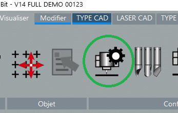
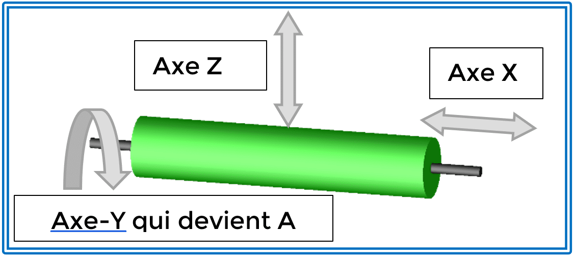
a. The Cylinder is oriented along the X axis (Horizontal), the Y axis is substituted with a rotative axis named A. This replacement operates through the activation of the following icon.
b. Click this icon to activate the 4th Axis output from TYPE EDIT.
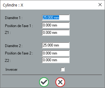
c. Cliquck next on the button “Cylindre/Cône…” so the next window opens allowing to define the size of the raw cylinder.
d. Enter the diameter of the cylinder in the Diameter 1. Keep the same Diameter for the Diameter 2 and then validate.
6. Activating the Automatic Vaccum:
a. Click on the next command to activate the vaccum (Active Position on this machines).
Additional Notes :
Regarding the lubrication, it is recommended to activate it directly on the machine interface or not at all from there too.
Need Further Assistance to Configure your Machine output towards Next?
The global network of reseller and Technical Support of TYPE EDIT is at your disposal.


